

Sync
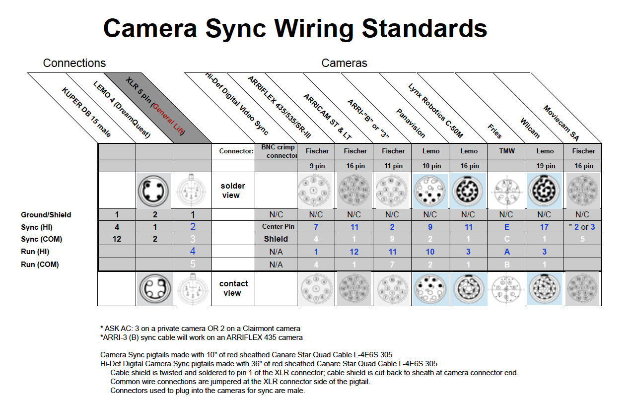
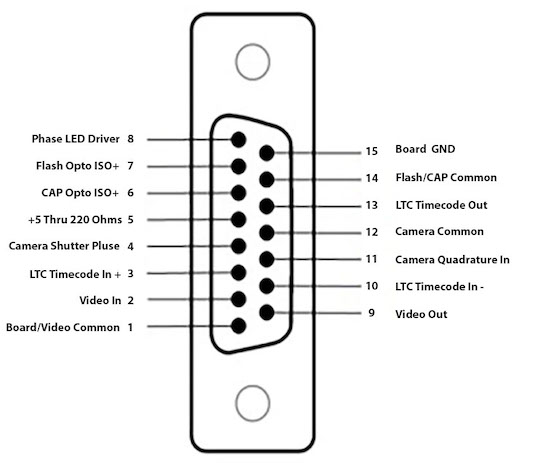
Different Pinout
*The pinout is slightly modified from RTMC48, please verify that there are no conflicting signals present on these pins:
Pin 8: Phase LED Driver
Pin 9: Video Out
Pin 11: Camera Quadrature In
Pin 13: Is now LTC Timecode Out. (on RTMC48 card, pin 13 was the "CAP-" Opto isolator output. It is important that any wire previously connect to pin 13 be moved to share pin 14.)
Timecode sync
"LTC Timecode in+" and "LTC Timecode in-" are capacitor isolated from the computer ground. For best noise immunity, do not connect either of these signals to the computer or board ground.
"LTC Timecode Out" is referenced to board ground.
Video sync
"Video In" is referenced to board ground. Either composite video or sync only may be used. In either PAL or NTSC format.
"Video Out" is referenced to board ground. It is the "Video IN" signal, with text information inserted. This signal is only present when a "video In" signal is being received.
Flash/Cap
"Flash Opto ISO+" and "CAP Opto ISO+" are the collectors of Opto isolated transistors, connected through 160 ohm resisters.
"Flash/CAP Common" is connected to the emitters. Do not connect either of these signals to the computer or board ground.
Film/Camera Shuttler sync
"Camera Shuttler Pulse" may be any once-per-frame, logic signal, from approcimately 5 to 24 Volts.
"Camera Quadrature In" is either the A or B phase from an encoder attached to the camera motor. Signal high should be between 5 to 24 Volts. The common is sharted between "Camera Shuttler Pulse" and "Camera Quadrature In".Both signals are optically isolated and no connection should be made to board or computer ground
The "Camera Quadrature In" connection is optional when syncing to external cameras. Its use enhances the ability of the motion control to track rapidly slewing cameras.
"Phase LED Driver" provides a convenient phasing signal for calibrating the phase relationship between an external camera and the motion control. Connect this signal directly to the LED to board ground. Drive is approximately 20 milliamperes at 5 volts. No resistor is required.
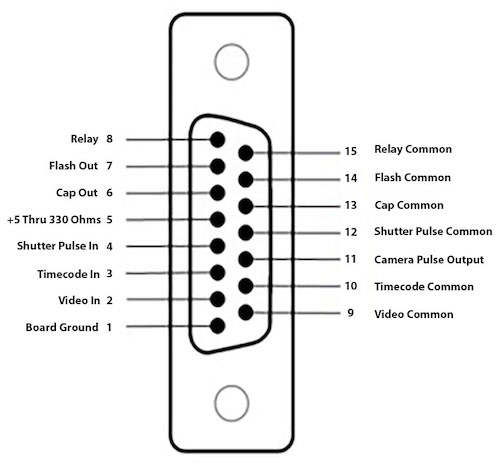
*Sync connections for sound speed camera motor:
All Connections are Pin-To-Pin, no signal conditioning is required.
Input impedance is 2000 Ohms.
*Timecode in and Timecode commom accept all longitudinal timecode formats.
Timecode should be of good quality and have a high signal level.
In order to maontain good timecode sync. The source should be a timecode generator or the "address Track" on a professional tape deck.
*Video in and Video comon connect directly to NTSC or PAL composite video. A 'Sync only" source is also acceptable.
*Relay and relay common are the unpolarized connects on a mechanical reply. Absolute maximum rating is 100 Volt DC. 500 milliamperes.
*Tipical of Cap and Flash output:
Absolute aximum rating: 40 Volt, 200 milliamperes.
Camera Sync wiring pdf downlaod
Kuper 2K Accessory DB15
Kuper RTMC48 Accessory DB15